|
Being a long time advocate of CW, I built my first ekectronic keyer back in the late 1950's. That was followed up in the mid-sixes with a "compact" electronic keyer using a pair
of 12AU7s. Desiring a solid state electronic keyer, a
"Ham Gadgets"
PicoKeyer Plus Kit was purchased and built. After a few years using the PicoKeyer, I wanted a touch operated keyer and decided that home brew modifications and add-ons to the
Picokeyer were the way to go. As with any home brew project, one should set definite goals as to the function, capability and ergonomic properties of the project. Using
my years of experience with an old war surplus J-38 hand key, an old war surplus navy bug and two diffenent tube based electronic keys, these goals were carefully developed. The
following criteria was adopted:
1) It should be a touch pad electronic keyer , not a logging do all integrated contest oriented package. 2) The PicoKeyer should be the "heart" of the keyer. No use to reinvent the wheel! The concept should be compatible with many keyer packages. 3) It should not be a hodge of boxes, wires and power supplies. 4) It should be neat, functional, and no larger footprint than bug. 5) Like a bug, it should be highly stable and not bounce around the table. 6) Like a bug, it should have self contained paddles and no external power source (implies an internal battery power source). 7) All adjustments, programming and any other functions should be easily accessible. 8) It should be highly adaptable as required for maintenance and/or modification. |
|
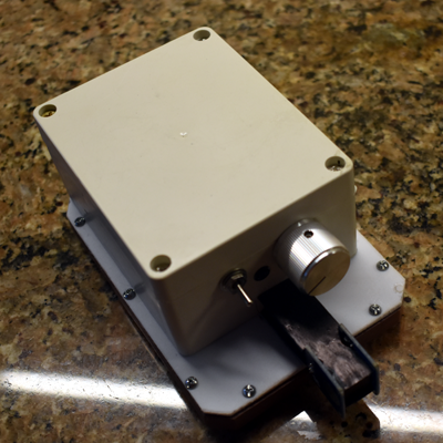
A
quick look at the finished product. |
|
Since touch operaton is driving this project, it seems like paddle design is a the place to start. A couple of TTP223 Capacitive Touch Pads were ordered and evaluated.
The TTP223 met the electronic requirements, but the early TTP223 used three header pins at right angles to the actual touch pad for connectors. This made it almost impossible to
use them fabricating keyer paddles. Turned in, the connectors spaced the actual touch parts of the pads a painfully wide distance apart. Turned out, mounting hardware spread the paddle
base much too wide for my needs. In addition, the touch circuity was mounted on one half of a rectangular pcb and the capacitive detector on the other half. This made the actual TTP223 much
too long for my tastes
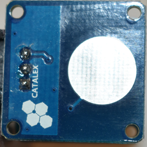
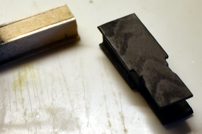
More searching was indicated and I found the CATALEX TTB223B; a nice square package with the circuitry arranged along one edge supporting a three pin right angle header. The actual TTP223B is a good keyer paddle size and the right angle pins allow the wiring to be hidden within supporting hardware. In the interest of the readers of this page, I have searched the internet for new CATALEX TTP233B Capacitive Touch Pads. None were found! However, a number of TTP223B Capacitive Touch Pads were found that look a twin. |
|
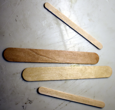
Several methods of mounting the touch pad paddles were tested tried out. Functionally and appearance were the major factors. Surprisingly the common craft sticks available at
hobby stores made wonderful paddle mountings. Using the tongue depressor and popsicle size fit the bill.
|
|
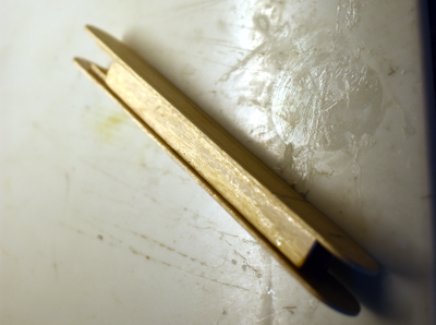
Glue the sticks together forming a sturdy tunnel.
|
|
Wait until the keyer box is mounted on the base, then determine how far out the paddles are desired. Carefully measure and cut a section of this length out of the tunnel. Trim
out the side pieces of one end to accept the TTP223B. Stain and finish the section. Engage one end of a 3 pin jumper wire on each TTP223B (one for dot, one for dash). Stuff the
other ends of the jumper wires down the tunnel and glue a TTB223B to both sides of the tunnel section. Cut a hole center bottom in the front of the keyer cabinet. Stuff the tunnnel
ends of the jumper wires through the hole and glue the tunnel section to the keyer base and cabinet.
oth
|
|
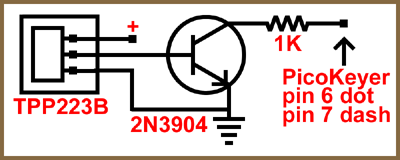
A simple 2N3904 switching circuit was designed to interface the TTB223B with my existing PicoKeyer Plus electronic keyer. This circuit was evaluated and the TT223B/PicoKeyer Plus
performed as expected.
|
|
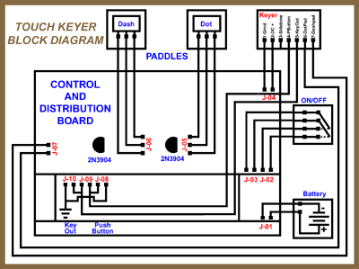
The main control and distribution board consists of two of the 2N3904 circuits (one for the dot paddle and one for the dash paddle) and a series of 2 or 3 pin headers. Watch
polarities and wire the headers together as indicated in the illustration to the right.
|
|
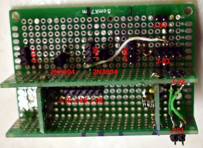
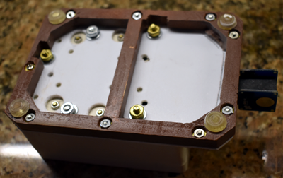
Main control and distribution panel wired as indicated in the previous illustration. Appropriate headers are labled in red.
|
|
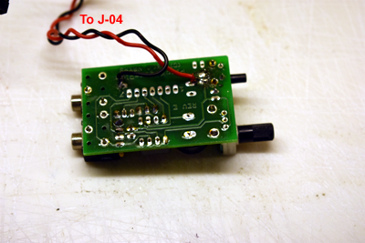
The PicoKeyer was examined and prepared for use in the Touch Pad Electronic Keyer. The coin cell pattern battery holder
was removed and stored in the parts bin. The PicoKeyer is designed with holes for a 7 pin header under the battery holder. Reviewing my existing stock of jumper wires, I decided
to forego installing a header. A single ended 2 pin jumper wire was soldered to the empty battery terminals. These wires go to J-04.
|
|
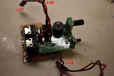
Turn the PicoKeyer board over. Solder a single ended 2 pin jumper wire to holes 6 and 7 in the 7 pin header row, these wires go to J-07. Now solder a single ended 2 pin jumper wire to holes 4 and 5
in the 7 pin header row, these wires go to J-09.
|
|
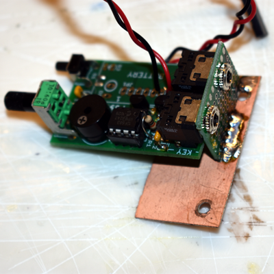
The PicoKeyer board needed additional support within the cabinet. A small right angle support was added to the board.
|
|
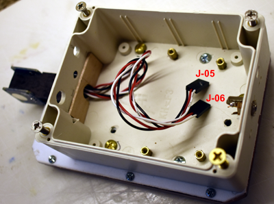
If not already done, it is time to pull the paddle wires into the cabiinet and securely glue the paddle mount to the keyer base. The paddle wires go to J-05 and J-06.
|
|
An attractive hardware base was finished and added to the keyer.
|
|
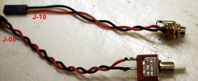
Solder a single ended 2 pin jumper wire to a momentary push button switch, these wires go to J-08 and are used to program the PicoKeyer. Solder a single ended 2 pin
jumper wire to an ouput jack, these wires go to J-10.
|
|
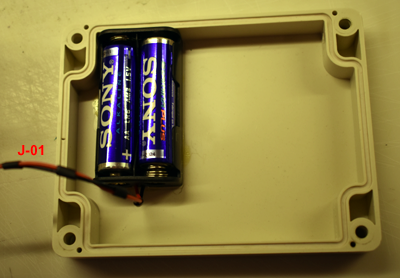
The battery pack with two AA batteries is glued to the top of the cabinet. The two wires are a single ended 2 pin jumper wire that goes to J-01.
|
|
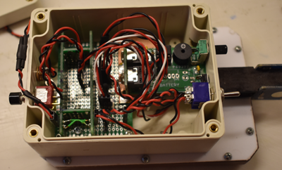
Plug all the wires to the appropriate headers. Mount the ouput jack on the back of the cabinet and plug onto header J-10. It is imperative that the output jack be
insulated from all the other boards as polarity must be reversed to key grid block tube amplifers. Mount the programming push button switch and plug it onto J-08. The
power plug can be seen curling from J-01 over the back of the cabinet. Put the top on the cabinet and stick a knob on the speed control. Enjoy!
|
|
>
Your browser does not support the <video> tag.
This is what makes all the work worth it! Half the fun is building it and making it work.
|


|