|
The vertical antenna described here preforms admirbly on six (6) bands. It could be extended to cover more bands,
but at the time six was my target goal. This was before age of 2,200 meters, 630 meters, 30 meters, 17 meters and 12
meters. It was also before the age of digital cameras, hence the lack of actual pictures. Only three pictures exist of
of the antenna components and they cannot be found.
|
|
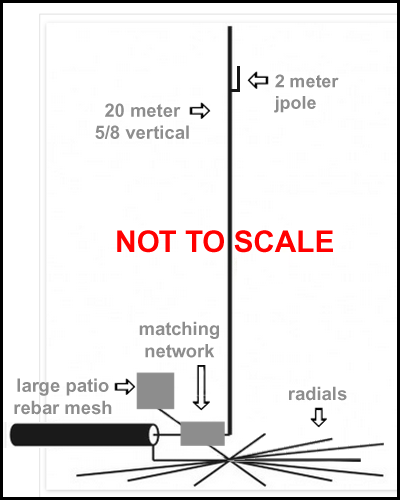
The basic antenna is a simple 20 meter 5/8 wavelength vertical. I used seven (7) radials alternating between 20 meter and 40 meter radials. I have not specified
length of the vertical in linear measurement since each construction site has to select material and apply the appropriate velocity factor.`
|
|
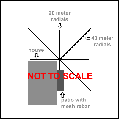
Six (6) radials were used alternating between 40 meter radials and 20 meter radials. The antenna was erected at the corner of the house, so one
quadrant did not have a radial. Also, one radial running parallel to the house was tied into the rebar mesh of a very large patio before the
concrete was poured.
|
|
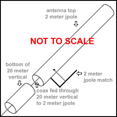
The upper part of the 20 meter 5/8 vertical is made into a 2 meter jpole antenna. RG-8U coax is fed up through the 20 meter 5/8 vertical and brought
out through a hole to feed the two meter jpole matching section. A conducting standoff attaches the 2 meter matching section to the main 20 meter 5/8
vertical antenna. An insulating standoff holds the matching section steady. In my case, the 20 meter 5/8 vertical was made from 1.5 inch TV mast
sections. The 2 meter matching section was made from half inch electrical conduit.
|
|
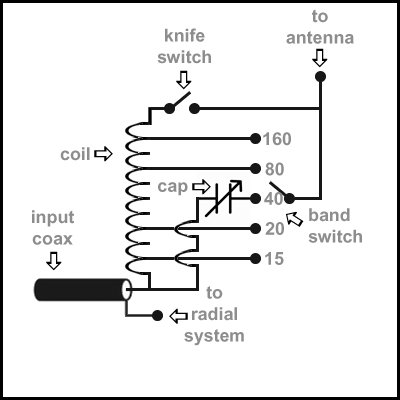
The matching network consists of four main parts. The heart of the network is the coil. A military surplus coil wound on a ceramic core about 2 inches in
diameter and 8 ten inches long was used. A surplus heavy duty bandswitch from an antenna control box was used for the band switch; and yes, it only had
five posistions. The tuning capacitor was salvaged from a gutted ARC5 transmitter and was about 150 mmfd. The knife switch was one of those old fashioned
manual throw switches with a pivoting arm on a heavy ceramic base. The arm had an insulating handle. You simply grabbed the handle and pulled it open, or
closed it. It was left over in my junk box from childhood.
The coil acts as a loading coil on all bands except 40 meters. The knife switch shorts out the unused portion of the coil. In my case, 40 meters needed only capacitve reactance for matching, so only the capacitor is used in the circuit. The knife switch has to be opened, or the capacitor is shorted out. A run of RG8U coax was used from the matching network to the transceiver. The entire matching network was housed in a wooden box with an access door. The box used bottom openings for ventalation to reduce sweating. |
|
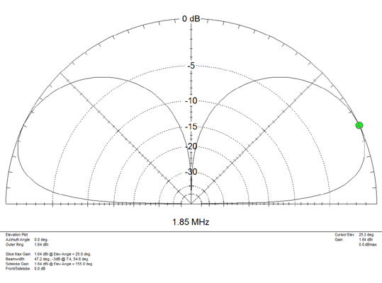
The elevation plot shows maximum gain of -1.64 dBi at an angle of 25 degrees. Of more interest is the beamwidth of 47.2 degrees between the -3dB points of
7.4 degrees and 54.6 degrees. The antenna gives outstanding low angle performance on 160 meters.
|
|
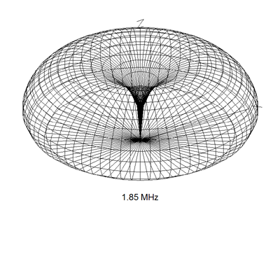
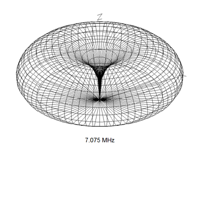
Looking at the 3D donut plot, the antenna theoretically displays a perfect omnidirection pattern with no nulls. In the real world, this can not
be true due to a plethora of factors; house effects in one (x,y) quadrant to start with and an inadaquate radial system to mention only two. Actual
performance and field strength measurments (though sparse and not a scientific study) leads one to believe that including the rebar mesh of a very
large patio in the radial system helped cure some of these problems.
|
|
The elevation plot shows maximum gain of -.76 dBi at an angle of 26 degrees. Of more interest is the beamwidth of 46.2 degrees between the -3dB points of
8.5 degrees and 54.7 degrees. These figures are very similar to those on 160 meters except for increased gain factor of -.76 dB. Real
world performance showed surprising good results.
|
|
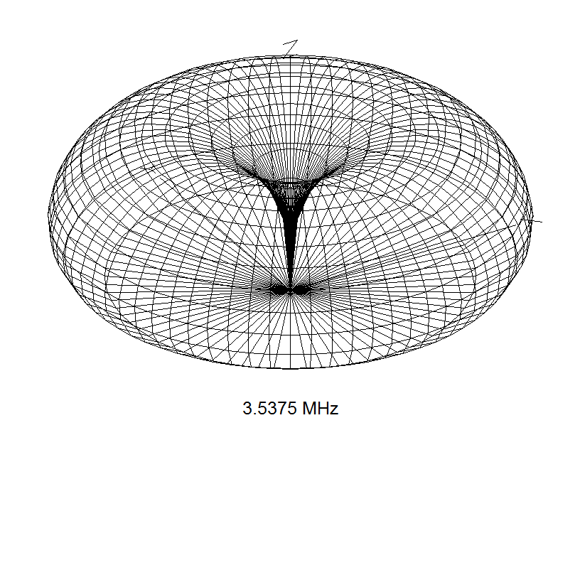
Looking at the 3D donut plot, the 160 meter comments apply.
|
|
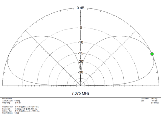
The elevation plot shows maximum gain of -.11 dBi at an angle of 24 degrees. Of more interest is the beamwidth of 40.8 degrees between the -3dB points of
8.6 degrees and 49.4 degrees. These figures are very similar to those on 160 meters except for the gain factor of is coming up to -.11 dB. Real
world performance showed this gain increase.
|
|
Looking at the 3D donut plot, the 160 meter comments apply.
|
|
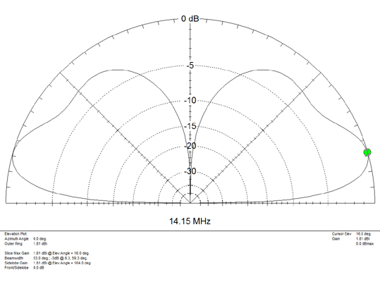
The elevation plot shows maximum gain of 1.81 dBi at an angle of 16 degrees. Of more interest is the beamwidth of 53.0 degrees between the -3dB points of
6.3 degrees and 59.3 degrees. These figures are very encouaging, especially the highest gain factor of 1.81 dBi and a usable 6.3 degree low angle radiation. Real
world usage showed the improved performance.
|
|
Looking at the 3D donut plot, the 160 meter comments apply.
|
|
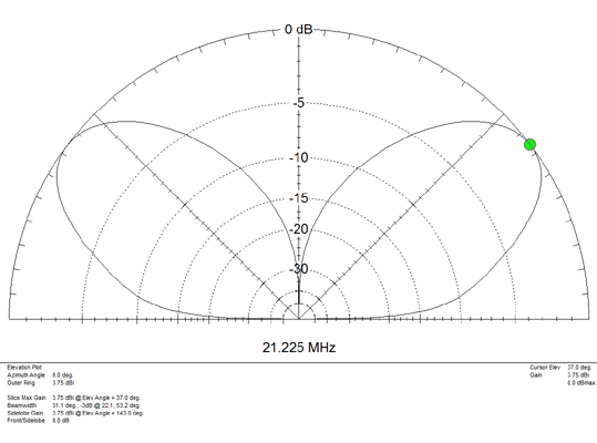
The elevation plot shows maximum gain of 3.75 dBi at an angle of 37 degrees. Of more interest is the beamwidth of 31.1 degrees between the -3dB points of
22.1 degrees and 53.2 degrees. These figures are very encouaging, especially the highest gain factor of 3.75 dBi, but the high angle of radiation ia a real
disapointment. Real world usage has been limited.
|
|
Looking at the 3D donut plot, the 160 meter comments apply.
|


|